How to Machine Parts on a CNC Lathe
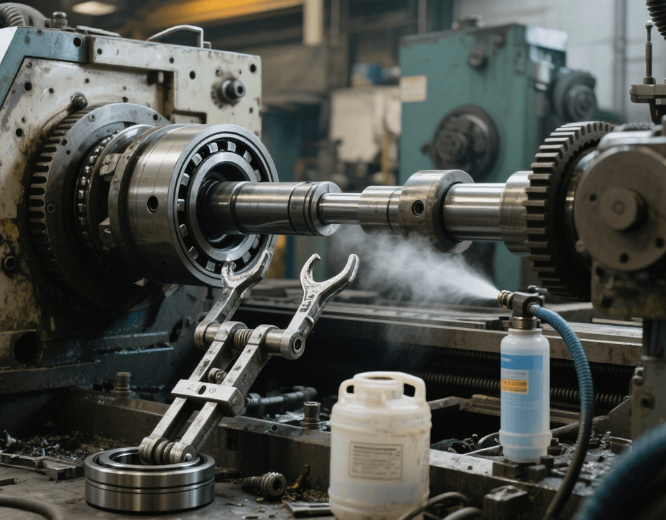
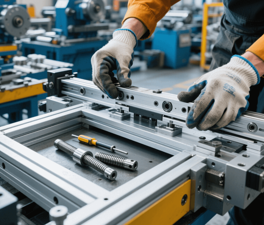
In precision parts machining factories with Swiss – type lathes as the core equipment, CNC lathe machining is a key technology for achieving high – precision rotary parts. From auto parts to medical device components, CNC lathes, with their advantages of high automation and good repeatability, have become the preferred equipment for mass production. The following details the entire process and key technical points of machining parts on a CNC lathe based on factory practices.
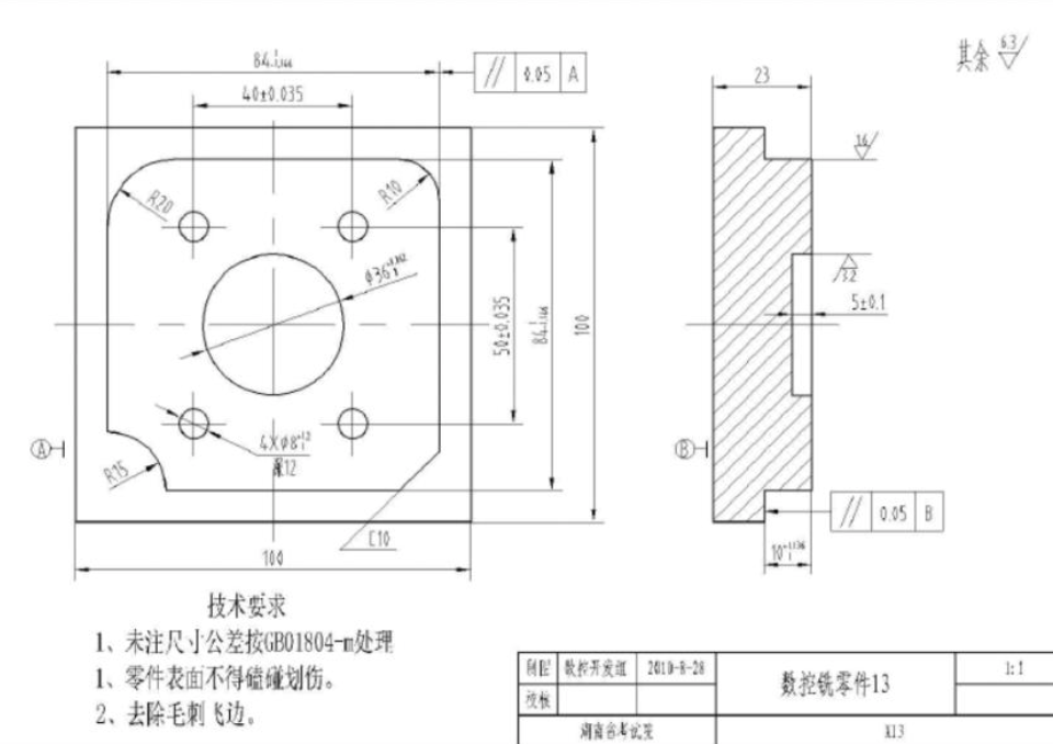
I. Preliminary Preparations: Drawing Analysis and Process Planning
1. Part Feature Analysis
First, clarify the geometric features of the part:
* Shaft – type parts: Pay attention to diameter tolerance (such as ±0.01mm) and cylindricity (≤0.005mm);
* Disk – type parts: Focus on end – face flatness (≤0.02mm) and hole coaxiality (≤0.01mm).
Take a motor shaft as an example; it needs to meet the requirements of dimensional accuracy and surface roughness (Ra≤0.8μm) of the mating journal simultaneously.
2. Process Path Design
* Clamping scheme: For slender shafts with a length – diameter ratio > 5, double – center – pin clamping is adopted to reduce radial run – out;
* Machining sequence: Follow the principle of “roughing first, finishing second; main features first, secondary features second”. Leave a rough – turning allowance of 0.5 – 1mm, and finish – turning is carried out in 2 – 3 passes.
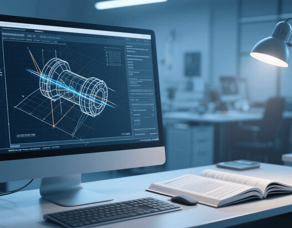
II. CNC Programming and Parameter Setting
1. Program Compilation
When programming with FANUC or SIEMENS systems, note:
* Application of G – codes: G71 is used for external – diameter roughing, and G70 executes the finish – turning cycle;
* Tool compensation: Call tool radius compensation through the T – code (such as T0101) to correct the tool – nose arc error.
2. Optimization of Cutting Parameters
During the machining process on a CNC lathe, cutting parameters for different machining stages need to be set scientifically:
* Rough – turning stage: The spindle speed is controlled at 2,000 – 4,000r/min, the feed rate is 0.2 – 0.4mm/r, the cutting depth is 1 – 3mm, and emulsion (10% concentration) is used for cooling.
* Finish – turning stage: The spindle speed is increased to 4,000 – 8,000r/min, the feed rate is reduced to 0.05 – 0.1mm/r, the cutting depth is 0.1 – 0.5mm, and minimum quantity lubrication (MQL) is used for cooling.
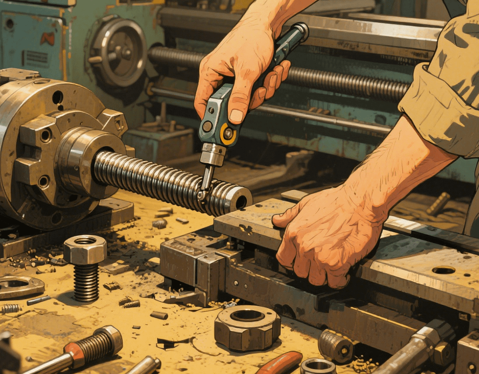
III. Key Machining Technologies
1. Precision Clamping Technology
* Hydraulic chuck: The clamping force is evenly controllable, suitable for disk – type parts (repeat positioning accuracy ≤0.003mm);
* Spring collet: Used for shaft – type parts with φ1 – φ20mm, and the clamping accuracy can reach ±0.005mm.
2. Cutting Vibration Control
* Tool overhang: Control the tool shank extension length to be < 4 times the diameter to avoid cutting chatter;
* Parameter adjustment: When chatter marks appear, reduce the feed rate by 10% – 20% or increase the principal cutting edge angle (such as changing from 90° to 95°).
IV. Quality Inspection and Process Optimization
1. On – line Inspection
* Infrared temperature measurement: Monitor the temperature in the cutting area (≤150℃) to prevent part thermal deformation;
* Tool – setting gauge: Automatically detect the tool wear amount (give an alarm when the tool – nose wear > 0.1mm).
2. Off – line Inspection
* Roundness measuring instrument: Detect the roundness of shaft – type parts (≤0.002mm);
* Surface roughness tester: Ensure that the surface quality meets the requirements of the drawing (such as Ra0.4μm).
In CNC lathe machining, through scientific process planning, precise programming, and strict process control, stable production of parts with micron – level accuracy can be achieved. Our factory is equipped with multiple high – precision CNC lathes and Swiss – type lathes, with over 10 years of experience in precision parts machining. We provide one – stop solutions from drawings to finished products for customers, meeting the needs of high – end fields such as aerospace and medical equipment.