How to Program Parts in CNC Systems
In the field of Swiss-type lathe precision machining, the accuracy of CNC system programming directly determines part precision and production efficiency. Based on our factory’s ten years of processing experience, scientific programming can reduce single-piece processing time by 25% and lower the rejection rate to below 0.3%. The following details the full process of CNC system programming from basic concepts to practical applications.
I. Pre-Programming Preparations
1. Drawing Analysis and Process Planning
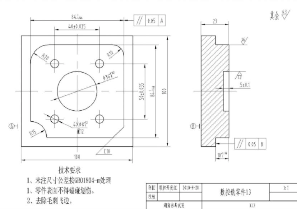
When receiving part drawings, key parameters such as dimensional tolerances (e.g., ±0.002mm) and surface roughness (Ra0.4μm) must be marked. The process route is selected according to part complexity—for example, shaft parts preferably adopt the Swiss-type lathe’s “one clamping for multiple processes” mode to reduce repeated positioning errors.
2. Tool and Parameter Matching
Select corresponding tools based on material properties (e.g., 304 stainless steel, titanium alloy TC4), such as carbide-coated end mills. Set parameters via tables or empirical formulas: for aluminum alloys, the spindle speed is 20,000r/min with a feed rate of 0.08mm/r; for steel, the cutting depth should be controlled within 0.5mm.
II. Core Programming Steps
1. Coordinate System Setting
Establish a workpiece coordinate system (G54-G59) in the CNC system, aligning the programming zero point with the part’s datum point. For symmetric parts, enable the mirror function (G51.1) to reduce repetitive programming workload.
2. Code Writing Techniques
* Linear and Circular Interpolation: When using G01 (linear) and G02/G03 (clockwise/counterclockwise circular) commands, node coordinates must be calculated precisely with an error control of ±0.001mm;
* Cycle Instruction Application: Invoke the G92 cycle for thread turning and the G73 deep hole pecking cycle for cavity milling to improve programming efficiency;
* Macro Program Writing: For regularly changing features (e.g., equidistantly distributed holes), implement parameterized programming through variable operations (#1, #2, etc.).
III. Simulation Verification and Optimization
1. Virtual Machining Testing
Import NC codes into simulation software like VERICUT to simulate tool paths and check for interference or collisions. In a programming case for an automotive sensor bracket, simulation identified a collision risk between the tool and fixture in advance, avoiding actual processing losses.
2. Code Optimization Strategies
Delete redundant instructions and merge continuous similar operations. Optimizing scattered linear interpolation commands into continuous contour machining can increase processing efficiency by 15%.
IV. Actual Machining Debugging
Adopt single-segment operation mode for the first trial cut, adjusting cutting parameters step-by-step. Use a tool setter to accurately measure tool length compensation (H code) and radius compensation (D code) to ensure first-piece qualification. Our factory has programmed and machined micro shaft parts for minimally invasive surgical instruments in the medical industry, successfully controlling key dimensional errors within ±0.001mm to meet strict medical standards. In the automotive sector, programming for fuel injection system parts reduced the single-piece production cycle by 20% through optimized programming processes, helping customers achieve efficient mass production.
Mastering CNC system programming technology is key to achieving precision machining. Equipped with mainstream CNC systems like FANUC and SIEMENS, our factory supports one-stop services from drawing design, programming debugging to mass production, having completed programming and machining for over 500 complex parts in medical, automotive, and other industries to ensure 100% compliance with drawing requirements.