How to Perform CNC Machining on Aluminum Parts
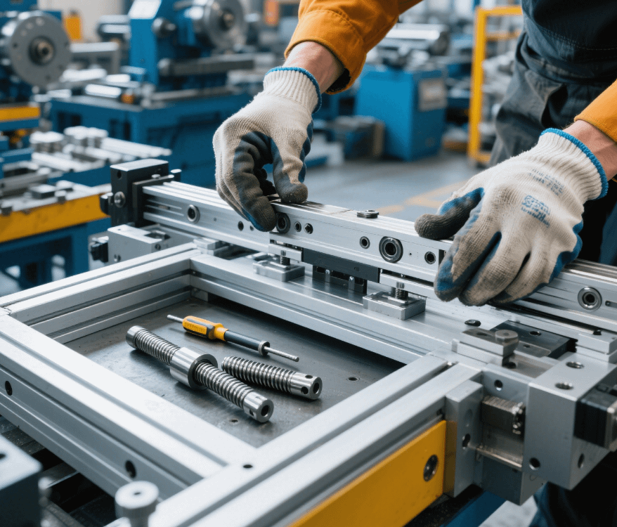
In our factory specializing in machining precision parts with Swiss-type lathes, aluminum parts are frequently processed due to their characteristics of light weight, easy machinability, and good electrical conductivity. However, aluminum’s soft material, low melting point, and tendency to deform and stick to tools during machining require targeted process adjustments. Below are the key points and operation guidelines for CNC machining of aluminum parts.
I. Material Characteristics and Tool Selection
1. Machining Characteristics of Aluminum
Aluminum has a density of approximately 2.7 g/cm³ and low hardness (e.g., 6061 aluminum alloy has a hardness of about 95 HB). It has good thermal conductivity but is prone to plastic deformation during cutting, leading to reduced surface roughness. Additionally, aluminum chips are highly sticky and easily adhere to the tool edges, forming “built-up edges” that affect machining accuracy and tool life.
2. Key Points for Tool Selection
* Tool Materials: Prioritize carbide (YG series) or diamond-coated tools. Diamond coatings significantly reduce surface friction and minimize tool sticking, while high-speed steel tools are only suitable for low-load machining.
* Tool Geometric Parameters:
* Rake Angle: Increase the rake angle (e.g., 15°–25°) to reduce cutting resistance and deformation.
* Relief Angle: Set the relief angle to 8°–12° to avoid friction between the tool and the machined surface.
* Edge Radius: Maintain a sharp edge with a 0.02–0.05 mm chamfer to prevent edge chipping.
* Typical Tools: End mills with a helix angle of 30°–45°, and mirror-finish boring tools (for high-precision hole machining).
II. Process Parameter Optimization
1. Setting of Cutting Parameters
* Spindle Speed: 2000–6000 r/min. Lower-hardness aluminum allows higher speeds, but excessive speeds should be avoided to prevent tool overheating and wear.
* Feed Rate: 800–3000 mm/min. Higher feed rates reduce chip dwell time on the tool edges to minimize sticking, but they must match the machine tool’s rigidity.
* Cutting Depth: Rough machining: 1–5 mm; finish machining: 0.1–0.5 mm. Rough machining removes excess material quickly, while finish machining leaves a small allowance to avoid deformation.
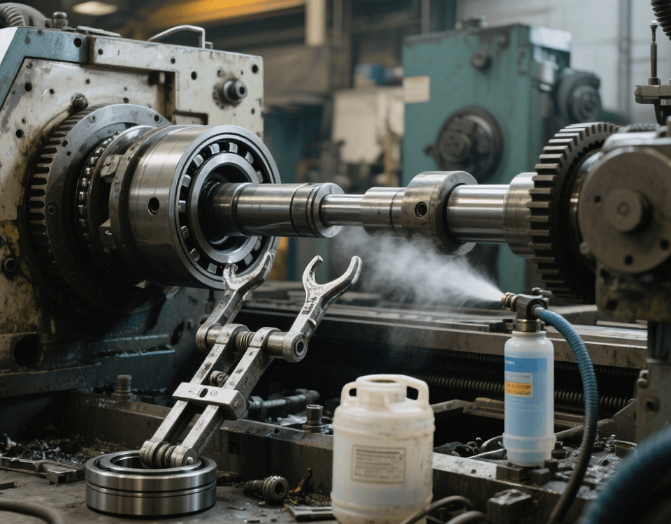
2. Cooling and Lubrication
* Cutting Fluid Selection: Use water-soluble or semi-synthetic cutting fluids, which offer better cooling and cleaning performance than oil-based fluids, effectively flushing away aluminum chips and reducing cutting temperatures.
* High-Pressure Cooling: For deep-cavity or complex-structured parts, apply high-pressure cooling (5–20 MPa) to spray cutting fluid directly onto the cutting area and prevent chip accumulation.
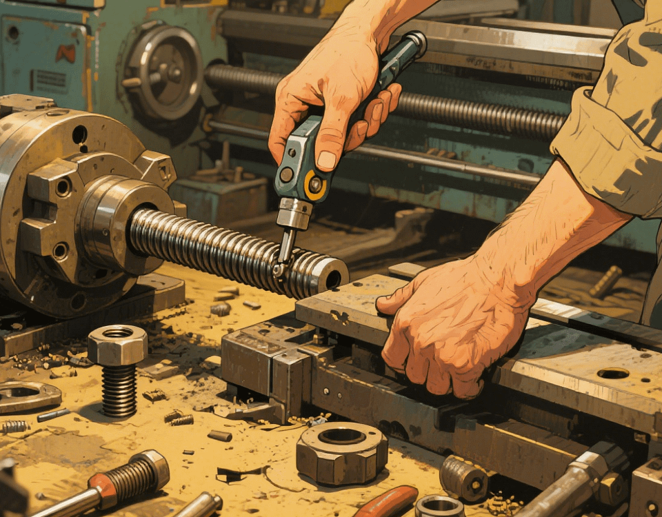
III. Clamping and Deformation Control
1. Fixture Design Principles
* Avoid Single-Point Clamping: Use vacuum chucks or elastic fixtures to distribute clamping force evenly and reduce deformation of thin-walled parts. For example, when machining aluminum aerospace structural parts, vacuum chucks can evenly adsorb flat surfaces via negative pressure, avoiding local deformation caused by traditional vise clamping.
* Positioning Reference: Use machined surfaces as positioning references to ensure secure clamping. For large parts, add auxiliary support points (e.g., nylon blocks) to prevent vibration at overhanging ends.
2. Deformation Prevention Techniques
* Layered Cutting: For thick-walled parts, adopt a strategy of “multiple roughing passes + gradual finishing,” with each cutting depth not exceeding 30% of the tool diameter to release internal stress.
* Stress Relief Annealing: For high-precision parts, perform stress relief annealing (180°C × 2 hours) after rough machining before finishing to reduce post-machining deformation.
IV. Machining Path and Tool Path Planning
1. Avoid Vertical Plunging
Aluminum chips tend to accumulate at the tool bottom, and vertical plunging may cause tool breakage. It is recommended to use helical plunging (helix angle 5°–10°) or ramp plunging (ramp angle 3°–5°) to gradually 切入 (plunge into) the material.
2. Selection of Up Milling and Down Milling
* Down Milling Priority: Down milling, where the tool 切入 (plunges into) from the machined surface with a cutting thickness decreasing from thick to thin, reduces tool wear and workpiece springback, suitable for finishing.
* Up Milling Scenarios: Use up milling for cast aluminum workpieces with hard skin or oxide layers to avoid tool impact on hard spots.
3. Chip Removal Strategy
When machining deep cavities or narrow slots, retract the tool to a safe height and move rapidly after each cutting layer to flush away aluminum chips with cutting fluid, preventing chip accumulation that may cause tool wear or workpiece scratches.
V. Typical Case: Machining Process for Aluminum Impeller
1. Blank Preparation: Use forged aluminum (e.g., 7075-T6) with pre-applied aging treatment.
2. Rough Machining: Use a ϕ20 mm carbide end mill for helical plunging, cutting layer by layer to leave a 0.5 mm allowance from the final dimension.
3. Semi-Finishing: Switch to a ϕ10 mm ball end mill for contour milling of blade surfaces, leaving a 0.2 mm finish allowance.
4. Finishing: Use a diamond-coated end mill for streamline milling at 5000 r/min and 2000 mm/min feed speed to ensure a surface roughness of Ra≤0.8 μm on the blades.
5. Inspection: Measure blade profile accuracy with a coordinate measuring machine (CMM) to ensure errors within ±0.01 mm.
VI. Common Issues and Solutions
* Poor Surface Roughness: Caused by built-up edges or tool wear. Solutions: Increase cutting speed, use coated tools, and enhance cooling pressure.
* Dimensional Deviation: Caused by clamping deformation or thermal expansion. Solutions: Optimize fixture design and control cutting temperature.
* Short Tool Life: Caused by improper cutting parameters. Solutions: Reduce cutting depth and increase rake angle.
Through the above process optimizations, our factory can stably machine various aluminum precision parts, from aerospace structural components to electronic heat dissipation parts, meeting strict precision requirements (e.g., IT7 tolerance grade). For specific machining solutions, please contact us for customized services.