How to Develop CNC Programs Based on Parts
In the field of Swiss-type lathe precision machining, developing CNC programs based on parts is a critical link in transforming design into production. A scientific programming process can convert tolerance requirements (such as ±0.01mm) from part drawings into precise instructions executable by machines. The following details the full-process technical solutions from parts to CNC programs, using automotive fuel injection system components as examples based on the factory’s 15 years of practical experience.
I. Part Process Analysis
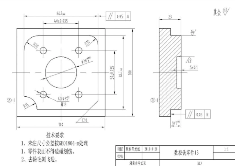
1. Drawing Information Extraction
* Geometric Features: Identify key elements of automotive fuel injector parts, such as φ0.3mm injection holes, M12×1 fine-pitch threads, and R3mm transition arcs;
* Precision Requirements: Specify special parameters for fuel systems, such as surface roughness Ra≤0.2μm (inner wall of injection holes) and roundness ≤0.005mm.
2. Machinability Evaluation
* Tool Accessibility: For micro-holes with a length-diameter ratio >20 (e.g., φ0.5mm×12mm), select cemented carbide micro-hole drills (length-diameter ratio 25:1);
* Clamping Scheme: Adopt elastic collets (clamping force ≤3N) combined with axial positioning to avoid deformation of thin-walled structures (wall thickness 0.8mm).
II. Preparations for CAM Programming
1. 3D Model Construction
* Forward Design: Use UG NX to draw 3D models according to drawings, focusing on restoring the taper (15°) and chamfer (C0.1mm) of injection holes;
* Reverse Reconstruction: Generate point clouds for sample parts using a blue-light scanner (accuracy 0.01mm), and fit surfaces through Geomagic software.
2. Process Planning Table Formulation
In the CAM programming preparation stage, a detailed process planning table shall be formulated to clarify the processing content, tool models, spindle speed, and feed rate for each process:
* Process 1: Face turning, using CCMT09T304 tool, spindle speed 12,000r/min, feed rate 0.08mm/r;
* Process 2: Outer circle finish turning, using TNMG160404 tool, spindle speed 15,000r/min, feed rate 0.05mm/r;
* Process 3: Micro-hole machining φ0.3mm, using φ0.3mm cemented carbide drill, spindle speed 30,000r/min, feed rate 0.01mm/r.
III. CNC Program Generation Technology
1. Automatic Programming Operations
* Tool Path Design:
* Adopt G71 cycle for outer circle machining (back engagement 1mm, leaving 0.2mm finish turning allowance);
* Use G83 deep hole cycle for micro-hole machining (retracting 2mm for chip removal each time, pause time 2s).
* Parametric Programming: Achieve dynamic adjustment of micro-hole diameter through #101=0.3+#102 (#102 is the wear compensation amount).
2. Special Structure Handling
* Fine-Pitch Thread Machining: Use G92 cycle (pitch 1mm), set 4 feeds (back engagement 0.6mm, 0.3mm, 0.15mm, 0.05mm respectively);
* Thin-Walled Ring Groove Machining: Adopt layered cutting (0.15mm per layer) combined with G03 spiral feeding (radius R2mm) to reduce radial force.
IV. Program Verification and Optimization
1. Virtual Simulation Detection
* Interference Check: Simulate injection hole machining with VERICUT software to ensure the safety distance between the drill and positioning fixture ≥3mm;
* Cutting Heat Analysis: Predict the temperature field during titanium alloy machining through Deform software, and set the cutting fluid flow ≥15L/min.
2. First-Piece Trial Cutting Correction
* Key Dimension Detection: Check the roundness of φ0.3mm holes with an image measuring instrument (when the measured value is 0.008mm, reduce the program feed rate by 10%);
* Surface Quality Optimization: If the inner wall roughness of the injection hole is out of tolerance, increase the finish drilling speed from 30,000r/min to 35,000r/min.
V. Typical Case: Programming for Automotive Fuel Injection Valve Sleeve
Programming key points for a certain type of fuel injection valve sleeve (material 17-4PH stainless steel):
1. Model Processing: Construct a pre-deformed model with a 0.02mm shrinkage in SolidWorks to compensate for heat treatment deformation;
2. Tool Selection: Adopt φ2mm ceramic end mill (grade CC6060) for inner groove machining;
3. Program Optimization:
* Use G73 chip-breaking cycle for rough machining (retraction 0.5mm);
* Add G41 tool radius compensation (compensation value 0.01mm) during finish milling of inner holes;
4. Verification Results: After machining, the injection hole position degree ≤0.015mm, meeting the National VI emission standard.
Developing CNC programs based on parts requires integrating process analysis, programming technology, and precision control. Our factory is equipped with Mastercam programming workstations and coordinate measuring equipment, providing one-stop services from interpretation of automotive parts drawings, tool path planning to program debugging. We have developed more than 2,000 complex part processing programs for automotive precision parts industries such as fuel injection systems and engine sensors, ensuring dual optimization of production efficiency and precision.


