How to Design Parts for CNC Systems
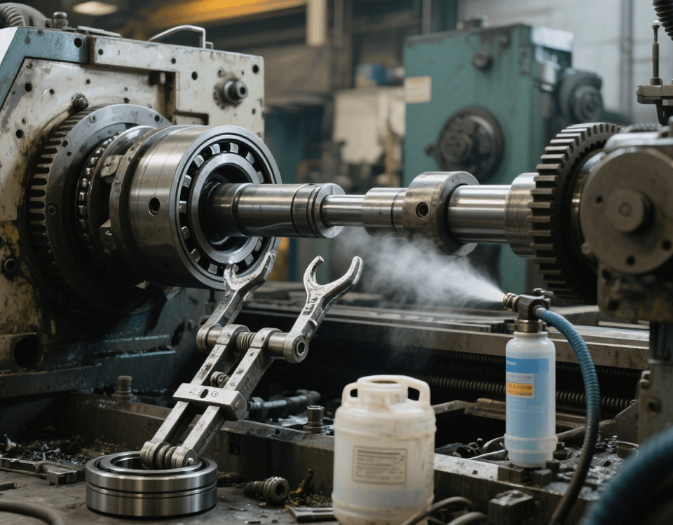
In the operation of a Swiss-type lathe precision parts machining factory, designing parts for CNC systems is a key link connecting product requirements with efficient production. CNC systems have special requirements for part machinability and precision matching, and scientific design methods can significantly improve machining efficiency and finished product qualification rates. The following details the core points and processes of designing parts for CNC systems based on factory practices.
I. Analysis of CNC Machining Characteristics
1. Understanding of Equipment Process Boundaries
Advantages of Swiss-Type Lathes: Suitable for slender shaft parts with a length-diameter ratio >20 (such as medical device drive shafts), enabling combined turning and milling processing;
Precision Limit: Typical machining tolerance is ±0.005mm (such as aerospace joint parts), and surface roughness Ra≤0.4μm.
2. Adaptability to Cutting Processes
Interference Avoidance: The depth of hole machining should not exceed 10 times the diameter (e.g., φ5mm hole depth ≤50mm) to avoid drill breakage;
Relief Groove Design: The thread end should reserve a relief space of ≥1.5 times the pitch (e.g., M10 thread relief groove width 2mm).
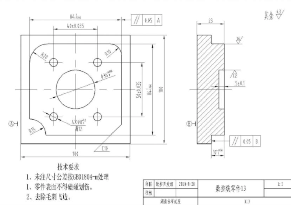
II. Design Criteria for Part Structures
1. Material and Structure Matching
Aluminum Alloy Parts: 6061-T6 material is recommended, and a hollow thin-wall design (wall thickness ≥1.5mm) is adopted in the structure to reduce cutting deformation;
Titanium Alloy Parts: The angle of reinforcing ribs is designed to be 45°-60° (such as frame structures) to enhance rigidity and reduce cutting volume.
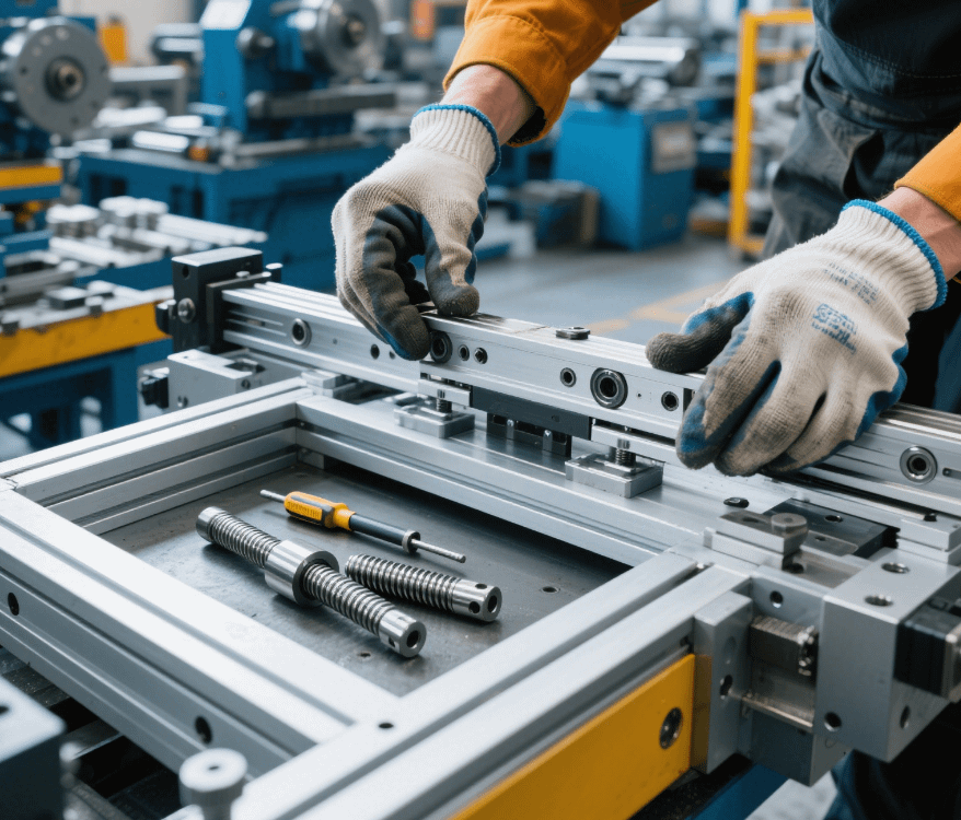
2. Standardization of Clamping Datums
Positioning Surface Design: Set 2 mutually perpendicular datum surfaces (flatness ≤0.01mm) for easy clamping by three-jaw chucks or vices;
Process Bosses: Add temporary bosses (size ≥10mm×10mm) to irregular parts, which are removed after machining.
III. CNC Programming-Friendly Design
1. Parametric Processing of Features
Hole System Design: Holes of the same diameter are arranged in an array (such as 6 holes evenly distributed in a circle) to facilitate G16 polar coordinate programming;
Unified Chamfers: C0.5 or C1 chamfers are preferred for edges to reduce tool change frequency.
2. Optimization of Cutting Allowances
Rough and Finish Machining Allowances: Leave 0.5-1mm rough turning allowance and 0.1-0.2mm finish turning allowance for the outer circle;
Thin-Wall Part Compensation: Reserve 0.03mm elastic deformation compensation in the diameter direction (such as φ30mm thin-wall sleeves).
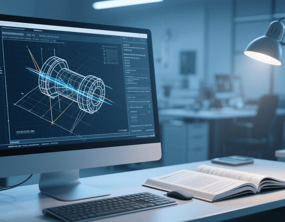
IV. Design Verification and Process Iteration
1. Virtual Machining Verification
Software Simulation: Use VERICUT software for cutting simulation to detect tool path interference (such as tool shank collision during cavity milling);
Cutting Force Calculation: Estimate cutting force through Deform software (e.g., titanium alloy milling force > 3 times that of aluminum alloy) to optimize tool selection.
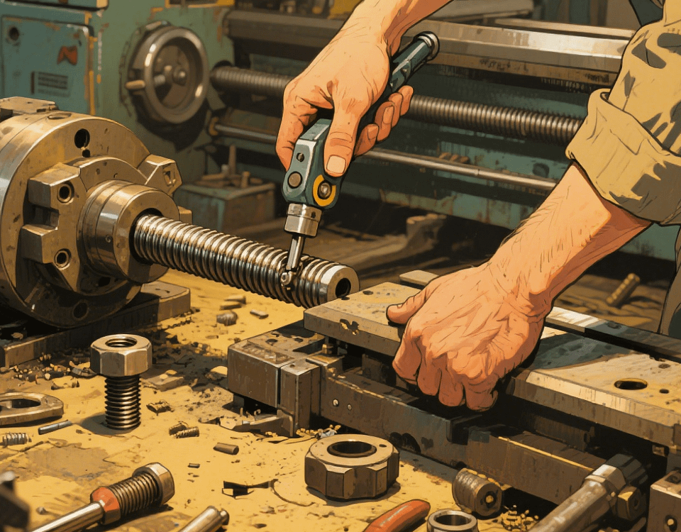
2. First-Piece Trial Cutting Optimization
Key Dimension Detection: Use a coordinate measuring machine to detect hole spacing (tolerance ±0.01mm) and thread pitch diameter (such as M8-6H);
Process Adjustment: Modify the design according to the trial cutting results (e.g., when the hole diameter tolerance is +0.02mm, change the drawing tolerance to +0.03/-0.01mm).
V. Typical Case: Automotive Sensor Shaft
CNC optimization design scheme for a certain automotive sensor shaft (material 6061, length-diameter ratio 15:1):
Structural Optimization: Design a φ2mm weight-reducing hole in the middle section (30mm from the end face) to reduce cutting vibration;
Clamping Design: Set φ5mm process center holes at both ends, matching double-center pin clamping;
Programming Optimization: Use G92 cycle for outer circle threads (pitch 1.5mm), increasing processing efficiency by 40%.
When designing parts for CNC systems, machining processes need to be integrated into the design stage. Our factory provides one-stop services from CAD design to CNC machining, equipped with a 3D design team and a complete production line of high-precision Swiss-type lathes. We can complete part machinability analysis and design optimization according to customer needs, ensuring both product precision and production efficiency.