How to Find Part Offset in CNC Machines
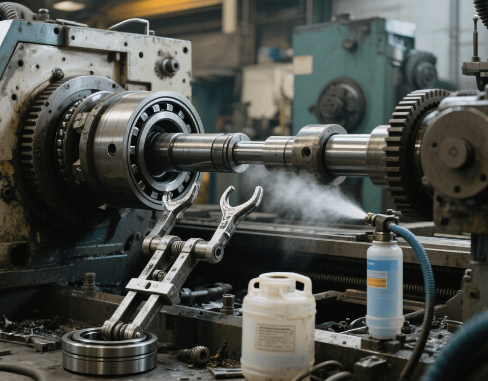
In Swiss-type lathe precision machining, accurately identifying part offsets in CNC machines is crucial for ensuring processing accuracy. Part offsets (such as X/Y axis positioning deviations or Z axis depth errors) can result from machine wear, thermal deformation, or programming errors. Scientific detection and compensation methods can control machining tolerances within ±0.01mm. The following details the full process of offset detection and correction based on factory practices.
I. Offset Types and Cause Analysis
1. Common Offset Types
Positioning Offset: Deviation between the actual and commanded axis positions (e.g., X axis moves 100mm but arrives at 100.02mm);
Posture Offset: Perpendicularity deviation between the spindle and worktable (e.g., wedge-shaped errors when milling planes);
Thermal Deformation Offset: Thermal elongation of the lead screw due to continuous machining (e.g., Z axis elongates 0.03mm at 80℃).
2. Typical Causes
Machine guide rail wear (offset increases by 0.005mm annually for equipment over 5 years old);
Cumulative cutting heat (offset ≥0.01mm when spindle temperature rises over 20℃ after 1 hour of continuous operation).
II. Precision Detection Tools and Methods
1. Hardware Detection Solutions
For detecting part offsets in CNC machines, the following hardware tools can be used, each with specific accuracy and application scenarios:
Laser Interferometer: Detection accuracy of ±0.5μm/m, suitable for full-travel positioning accuracy testing.
Electronic Level: Detection accuracy of 0.001mm/m, suitable for worktable flatness and perpendicularity testing.
Ball Bar: Detection accuracy of ±0.002mm, suitable for multi-axis 联动 posture offset testing.
2. Detection Process
Machine Preheating: Idle run for 30 minutes to thermally balance the spindle and lead screw;
Segmented Detection: Divide the stroke into 5 segments (e.g., 0-200mm), testing each segment 3 times and taking averages;
Data Recording: Use Excel tables to record differences between measured and theoretical values (e.g., X axis +0.015mm).
III. Offset Compensation Techniques
1. System Parameter Correction
Backlash Compensation: Input MD32450 parameter in FANUC systems (e.g., X axis backlash 0.008mm);
Pitch Error Compensation: Generate compensation tables via laser interferometer data (e.g., +0.003mm compensation per 50mm).
2. Programming Compensation Methods
G Code Correction: Add G10 L12 P1 X-0.015 at the program start (compensate X axis offset);
Macro Program Application: Achieve segmented compensation via statements like #100=#100-0.005*[#100/100].
IV. Dynamic Offset Control
1. Real-Time Thermal Deformation Compensation
Temperature Sensors: Install PT100 sensors at lead screw nuts (accuracy ±0.5℃), compensating 0.0015mm for each 1℃ temperature rise;
Cooling System: Activate spindle constant temperature circulation (control oil temperature ±1℃), reducing thermal offset by over 50%.
2. Wear Compensation Strategies
Tool Wear Compensation: Call wear values via T codes (e.g., X compensation -0.02mm in T0101);
Guide Rail Wear Compensation: Inspect guide rail straightness annually, grinding for repair if out of tolerance (restoring accuracy to 0.01mm/1000mm).
V. Typical Case: Offset Correction for a Swiss-Type Lathe
Detection Data: X axis full-travel (300mm) positioning offset +0.025mm, backlash 0.012mm;
Compensation Plan:
Input system parameter MD32450=0.012mm (backlash);
Generate pitch compensation tables (+0.008mm, +0.009mm, +0.008mm per 100mm);
Correction Result: Roundness of φ50mm shaft parts improved from 0.03mm to 0.008mm, meeting aerospace standards.
In CNC machining, periodic detection and precise compensation can control part offsets at the micron level. Our factory is equipped with laser interferometer and ball bar detection systems, offering machine accuracy calibration and offset compensation services. With over 11 years of precision machining experience, we ensure products meet strict requirements in medical devices, automation machinery, automotive parts, and other industries.