How to Replicate Old Metal Parts with CNC Machines
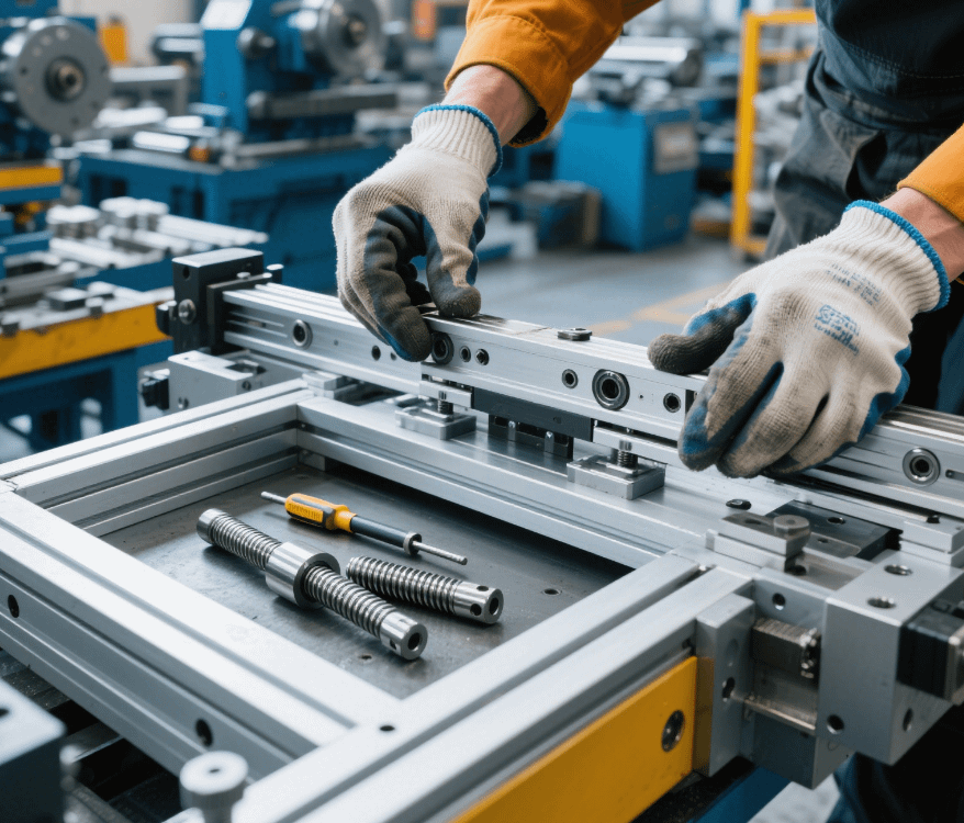
In the actual production of precision parts machining factories specializing in Swiss-type lathes, replicating old metal parts is a critical task integrating reverse engineering and CNC technology. These parts are commonly found in scenarios such as repairing old equipment or restoring antique machinery, with challenges including missing original blueprints and severe wear. The following details the complete process of replicating old metal parts using CNC machines based on factory practices.
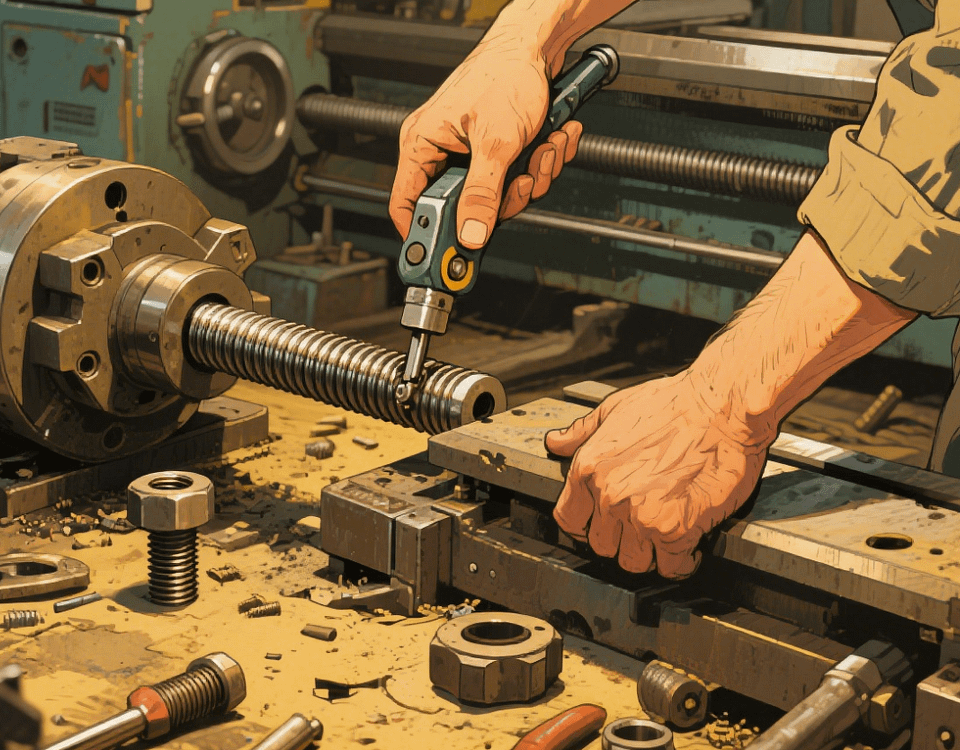
I. Part Pretreatment and Data Acquisition
1. Wear Assessment and Cleaning
First, inspect the old part visually and measure wear on key components using a dial indicator (e.g., shafts with diameter wear ≤0.1mm can be directly replicated). Use an ultrasonic cleaner (40kHz frequency) to remove surface oil and rust, ensuring accurate scanning data.
2. 3D Data Acquisition
Non-contact Scanning: Use a blue light 3D scanner (accuracy ±0.02mm) to scan the entire part, generating STL format point cloud data. For complex surfaces (e.g., turbine blades), scan in sections and stitch using Geomagic software.
Contact Measurement: Supplement critical dimensions (e.g., deep hole diameters, thread profiles) with a coordinate measuring machine (CMM) for non-scannable areas.
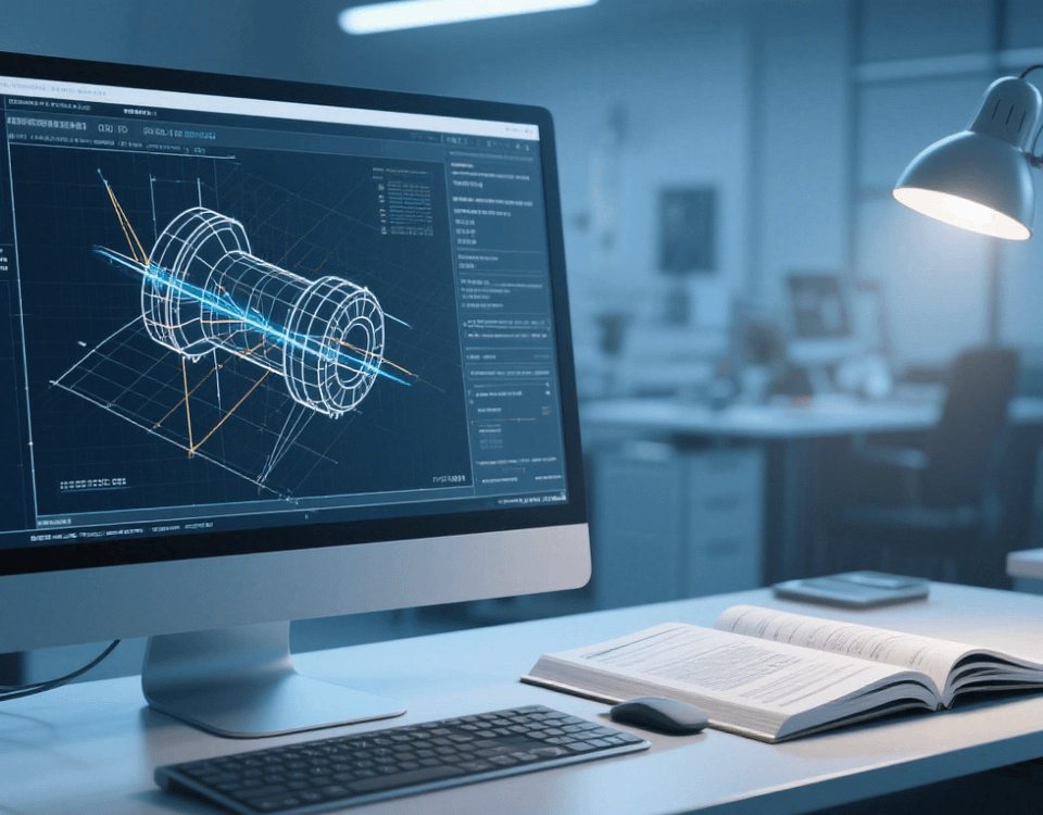
II. Reverse Modeling and Program Generation
1. 3D Model Reconstruction
Import point cloud data into SolidWorks for modeling:
Encapsulation: Remove noise, repair damaged surfaces, and generate polygon meshes.
Surface Fitting: Fit NURBS surfaces to regular features (e.g., cylinders, planes) with 误差 controlled within ±0.01mm.
Parametric Design: Adjust dimensions based on wear patterns (e.g., model shafts at nominal size +0.05mm).
2. CAM Program Generation
In Mastercam, configure based on the reconstructed model:
Machining Strategy: Adopt “residual roughing” to automatically avoid worn areas using scan data.
Tool Path: Generate cutting trajectories identical to the original part for features like threads and keyways to ensure assembly compatibility.
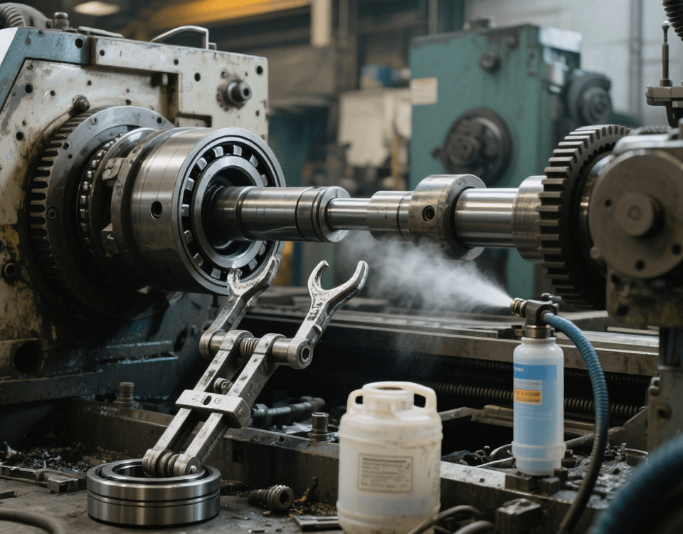
III. Key CNC Machining Technologies
1. Material and Tool Matching
Select substitute materials (e.g., QT450-10 for cast iron parts) and tooling:
Worn Part Machining: Use ceramic tools (e.g., CCMT09T304) to handle surface hardening.
Contour Machining: Employ form tools (e.g., R5 ball end mills) to replicate complex profiles, minimizing manual finishing.
2. Machining Parameter Adjustment
Tailor parameters for different machining stages:
Rough Contour Machining: Spindle speed 6,000–10,000r/min, feed rate 0.15–0.25mm/r, cutting depth 0.3–0.8mm, and increase coolant concentration to 12%.
Wear Surface Repair: Spindle speed 12,000–15,000r/min, feed rate 0.08–0.12mm/r, cutting depth 0.05–0.2mm, and activate machine vibration suppression.
IV. Compatibility Verification and Optimization
1. Assembly Testing
Assemble the replicated part with original components and check:
Fit Clearance: Measure shaft-hole clearance with feeler gauges (e.g., allow ±0.01mm deviation for a 0.03mm design clearance).
Motion Interference: Test run the equipment to ensure smooth gear meshing and sliding.
2. Process Iteration
Optimize if assembly issues arise:
Data Correction: Manually add wear compensation (e.g., keyway width +0.02mm) to scan data.
Tool Adjustment: Switch to coated tools (e.g., TiCN instead of TiAlN) to match original surface roughness (Ra1.6μm).
In old metal part replication, high-precision restoration is achievable through 3D scanning reverse modeling and precise CNC machining. Our factory, with over 10 years of reverse engineering experience and a full suite of scanning, machining, and inspection equipment, offers complete replication solutions from worn parts to new products, meeting special requirements in machinery repair and cultural relic restoration.