How to Replace CNC Spindle Bearings: A Comprehensive Technical Guide
I. Preparations Before Replacement
1. Tools and Consumables
* Essential Tools: Bearing puller, hydraulic press, electromagnetic induction heater (temperature control range 80–100°C)
* Testing Equipment: Dial indicator (for radial runout), feeler gauge (for fit precision)
* Consumables: KLüber NBU 15 grease, aviation kerosene, dust-free cloths
2. Preliminary Steps
* Refer to the machine manual to confirm the bearing model (e.g., P4-class angular contact ball bearing) and fit tolerance.
* Mark the circumferential phase of the spindle and bearing with a marker pen to offset errors during reinstallation.
II. Core Steps for Removing Old Bearings
1. Safety Power-off
* Cut off the machine power and hang a warning sign. After confirming the spindle has completely stopped, remove the protective cover and transmission components (e.g., pulley).
2. Cold Dismantling (for interference ≤0.015mm)
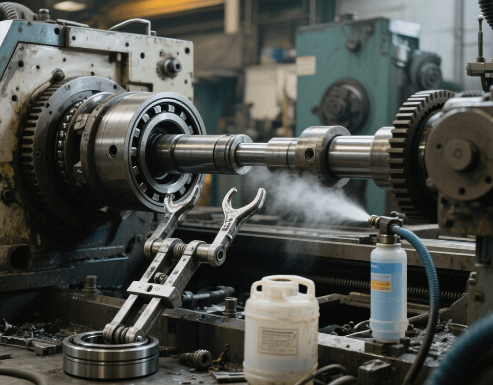
* Cool the bearing inner ring to -20°C with liquid nitrogen spray (maintain for 30 seconds) to reduce interference via thermal expansion and contraction.
* Install a synchronous puller with a guide device, evenly hook the inner ring end face with claws, and apply slow hydraulic force (≤5kN) until the bearing detaches from the spindle.
Note: In an automotive parts case, a non-synchronous puller caused journal scratches—prioritize professional tools with guides.
3. Hot Dismantling (for interference >0.015mm)
* Heat the bearing outer ring to 80°C with an electromagnetic heater (do not exceed 100°C to avoid bearing tempering softening).
* Gently tap the inner ring uniformly around the circumference with a copper bar, then remove the bearing after loosening with a wooden mallet.
III. Key Technologies for New Bearing Installation
1. Part Cleaning and Inspection
* Clean the spindle journal and bearing housing with aviation kerosene, then dry and inspect:
* Journal roundness ≤0.003mm, surface roughness Ra≤0.8μm
* Bearing housing cylindricity ≤0.005mm (detectable with feeler gauges)
2. Practical Oriented Assembly Method
* Use a dial indicator to detect spindle journal radial runout, mark the maximum runout point A.
* Detect the new bearing inner ring radial runout, mark the maximum runout point B.
* Assemble A and B at 180° to offset errors, ensuring total spindle runout ≤0.005mm.
3. Standard Hot Installation Process
* Heat the bearing to 80–100°C (constant temperature control, do not exceed 120°C).
* Apply a thin layer of ISO VG32 lubricant to the spindle journal.
* Press the bearing axially with a special sleeve to ensure precise positioning.
* After cooling to room temperature, use a feeler gauge to check axial clearance ≤0.002mm.
Case: A high-speed machining center using this process controlled spindle temperature rise at 1.5°C/h.
IV. Post-Assembly Testing and Debugging
1. Precision Verification
* Radial Runout: Detect at the spindle end with a dial indicator, should be ≤0.005mm.
* Axial Play: Measure under 50N axial force, should be ≤0.003mm.
* Temperature Rise Test: Idle for 30 minutes, temperature ≤40°C (at 25°C ambient temperature).
2. Common Abnormalities and Solutions
* Abnormal Noise: May result from bearing raceway damage—replace the bearing and check installation tools.
* Excessive Temperature Rise: Often due to overfilled grease—re-grease (fill 1/3 of bearing space).
* Unstable Precision: Usually from phase assembly errors—reassemble using the 180° error offset method.
V. Professional Technical Support
* Provide bearing model adaptation calculations (e.g., matching grease viscosity for 15,000rpm spindle speed).
* 3C Customer Case: Spindle bearing wear worsened surface roughness from Ra1.6μm to 3.2μm—restored to Ra0.8μm via oriented assembly.
* Offer fault diagnosis (e.g., vibration spectrum analysis) and emergency replacement plans.

